Development of Chemical Vapor Deposition Technology for the Synthesis of Carbon Nanomaterials
E.V.A. Premalal - Senior Lecturer (University of Sri Jayewardenepura)
Chemical Vapor Deposition (CVD) is a method in which a solid material is formed by the chemical reaction of vapor on or near a substrate surface, typically heated, within a vacuum or inert environment. The precursor gases, during their passage over the heated substrate (which may include a catalyst for deposition), undergo chemical reactions that lead to the formation of a solid phase, depositing onto the substrate. The temperature of the substrate and the growth pressure play crucial roles, influencing the occurrence of various reactions and their kinetics. In this context, it is presented here a newly developed multifunctional chemical vapor deposition system utilized for the synthesis of various carbon nanostructures. Carbon nanotubes, carbon nanostructures and carbon thin films were synthesized utilizing the developed CVD system.
Keywords: CVD, Carbon, Nanomaterial, Nanotubes, Thinfilm
Overview
Chemical Vapor Deposition (CVD) is a widely used technique for the synthesis of nanomaterials and thin films [1,2,3]. It involves the deposition of solid materials from a vapor phase chemicals reacting onto a substrate, resulting in the formation of a nanomaterial. In the synthesis of carbon nanostructures, catalysts are frequently employed within the reaction chamber to facilitate chemical reactions vital for the formation of nanomaterials [4,5]. The main components of a general CVD system comprise [6]
1. Reaction chamber surrounded by a heating element
2. Mass flow controllers (MFC)
3. Pressure gauge
4. Vacuum pump
5. Control valves
Figure 1 illustrates a typical Chemical Vapor Deposition (CVD) configuration, presenting its fundamental components.
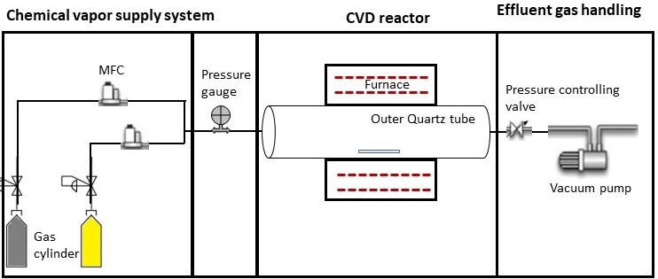
Figure 1. Schematic CVD configuration with its fundamental components
Quartz tubes or ceramic tubes are generally used as the reaction chamber along with a tube furnace surrounding it. The chemical vapor reacts with the catalyst or the substrate to form a new material. Specifically, numerous growth parameters such as temperature, pressure, and reaction time influence nanomaterial characteristics, including dimensions and properties.
Mass flow controllers define the flow rate of input gases. They are coupled with readers to digitally measure the flow rate in units of Standard Cubic Centimeters per Minute (SCCM). A digital flow controller is usually capable of controlling multiple gases using relevant conversion factors. However, there are analog MFCs, which are not currently popular and are limited to the gases for which they were calibrated.
The pressure gauge is used to monitor chamber pressure and is available in both digital and analog versions. A vacuum pump is used to maintain a vacuum in the chamber removing natural gasses or maintain inert gasses. A pressure-regulating valve adjusts the chamber pressure while the system is running.
Development of multifunctional CVD system
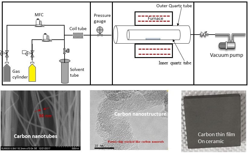
Versatile CVD system was developed as shown in the figure 2. It has various new additions compared to the conversional CVD system for easy and more controlled synthesis of Nanomaterials.
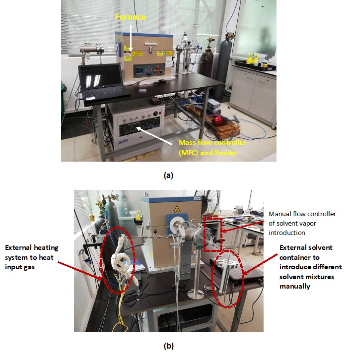
(b) Figure 2. Digital image of installed CVD setup view from (a) front side (b) Gas input side.
Modifications to conventional CVD system.
Introduction of solvent introduction unit
The synthesis of carbon structures requires only carbon feedstock gases and a catalyst-coated substrate in the CVD system. However, the introduction of various liquid vapors combined with carbon feedstock can significantly alter the properties and dimensions of the synthesized nanomaterials. For instance, the use of acetone vapor in conjunction with feedstock (C2H2) facilitates the synthesis of vertically aligned dense carbon nanotubes (CNTs).
However, supplying solvents to the system, apart from the pre-connected gas inputs, poses a challenge. In addressing this, we have introduced separate solvent introduction units, as illustrated in Figure 2 (b), to the system, allowing for easy changes in solvent compositions. This container was locally fabricated using stainless steel material (SS Grade 308). Ethanol (C2H5OH), methanol (CH3OH), and chloroform (CHCl3) have been introduced using the developed system. Solution flow rate was controlled using a manual flow controller, depicted in Figure 2 (b), where the unit was isolated using a ball valve. The complete separate solvent introduction unit was connected to the CVD system with an NW 50 vacuum fitting, as shown in Figure 2 (b).
Introduction of an external gas heating coil
The application of heat to input gases introduces an additional parameter for altering the synthesis of nanomaterials, potentially resulting in varied properties such as dimension and surface morphology. The heating of gases can modify reaction kinetics within the reaction chamber, leading to diverse dimensions and morphologies in the synthesized nanomaterials. For instance, in the process of producing dense, vertically aligned carbon nanotubes (CNTs), the heating of acetylene feedstock gas enabled efficient synthesis. To introduce the heating unit, stainless steel tubing has been converted into a spiral assembly incorporating an external heating coil, as illustrated in Figure 2b.
Introduction of the inner quartz tube and quick release NW50 vacuum flange to the system
A conventional CVD design typically involves a single quartz tube serving as the reaction vessel. However, this initial design presents challenges during chamber cleaning and material extraction, given the involvement of several components (flanges, pressure gauges, valves). Additionally, there is a possibility of material contamination when the setup is run multiple times. To address these concerns, we have introduced an inner quartz tube with a diameter 2 mm smaller than the external quartz tube, as illustrated in Figure 3. The cleaned inner tube, combined with the introduction of a catalyzed substrate to the system, enables the production of non-contaminated materials and facilitates easy material retrieval.
The inclusion of a quick-release NW 50 vacuum flange is another characteristic feature of the system. This design helps rapid assembly and disassembly of the system, allowing for the insertion and removal of inner quartz tubes from the reaction vessel.

Figure 3. Schematic diagram of outer quartz tube together with inner quartz tube.
Synthetization of nanomaterial from the developed CVD system.
Synthetization carbon nanotubes
Carbon nanotubes were synthesized using FeCl2 catalyst and C2H2 feedstock gas under the chamber growth conditions shown in the table below.
Substrate Temperature Growth pressure Feedstock/flow Rate
Quartz plate 800 C 3-10 torr C2H2/ 200 SCCM
SEM images and substrate of CNT array grown under these conditions are shown in figure 4. A vertically aligned CNT forest with a height of approximately 40 µm can be grown on quartz substrates using the specified growth conditions shown above.
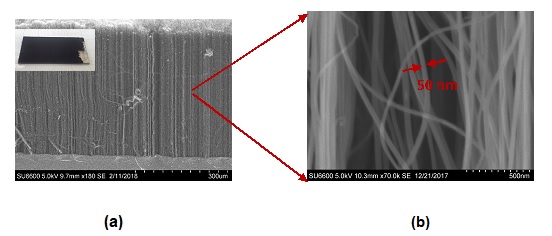
Figure 4. SEM image of the CNT array (a) inset with CNT substrate (b) at higher magnification.
Synthetization of Carbon nanostructures
Figure 5 displays the SEM image of a forest grown on the stainless steel (SS) substrate using Cu catalyst and acetylene feedstock gas, following the chamber growth conditions outlined in Table 2. It is interesting to note that micro-rods are formed by nanorods, as depicted in Figure 5
Substrate Temperature Growth Pressure Feeds stock/flow rate
SS 600-750 C 1-3 torr C2H2 /200 SCCM
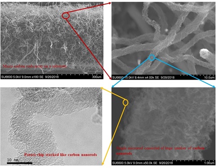
Figure 5. SEM image of an array of carbon rods and their respective zoomed images.
Synthetization of Carbon thin film
Figure 6 depicts carbon thin film coating on ceramic and stainless steel pieces using acetone vapor in the growth condition of temperature 700 C and acetone flaw rate 50 SCCM. It is interesting to note that the grown thin film exhibits electrical conductivity.
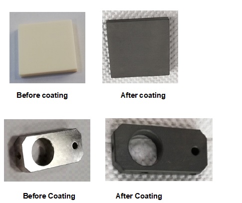
Figure 6. Image of carbon thin film coating on ceramic and stainless steel plate

E.V.A. Premalal
Senior Lecturer
Energy and Environmental Technology Section,
Department of Civil and Environmental Technology,
Faculty of Technology, University of Sri Jayewardenepura,
Pitipana, Homagama.